Welcome back to day 4 of 12 days of Arduino! I’m glad you’ve been following this far, things are about to get exciting! Today I take the keyboard and using a SN74HC595 Texas Instruments Shift Register I create a tremolo effect
Project requires
–Arduino Uno
–Active buzzer
–3x button touch switch
-220 ohm resistor
-3x 10k ohm resistor
-220 ohm resistor
-Jumper wires
-Tip120
-SN74HC595
SN74HC595 Shift Register datasheet.
Tip 120 datasheet from adafruit.
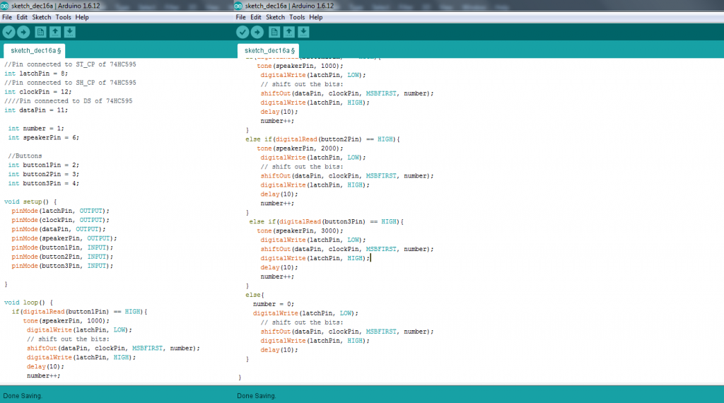
//Pin connected to ST_CP of 74HC595

int latchPin = 8;

//Pin connected to SH_CP of 74HC595

int clockPin = 12;

////Pin connected to DS of 74HC595

int dataPin = 11;
int number = 1;
int speakerPin = 6;
//Buttons
int button1Pin = 2;
int button2Pin = 3;
int button3Pin = 4;
void setup() {
pinMode(latchPin, OUTPUT);
pinMode(clockPin, OUTPUT);
pinMode(dataPin, OUTPUT);
pinMode(speakerPin, OUTPUT);
pinMode(button1Pin, INPUT);
pinMode(button2Pin, INPUT);
pinMode(button3Pin, INPUT);
}
void loop() {
if(digitalRead(button1Pin) == HIGH){
tone(speakerPin, 1000);
digitalWrite(latchPin, LOW);
// shift out the bits:
shiftOut(dataPin, clockPin, MSBFIRST, number);
digitalWrite(latchPin, HIGH);
delay(10);
number++;
}
else if(digitalRead(button2Pin) == HIGH){
tone(speakerPin, 2000);
digitalWrite(latchPin, LOW);
// shift out the bits:
shiftOut(dataPin, clockPin, MSBFIRST, number);
digitalWrite(latchPin, HIGH);
delay(10);
number++;
}
else if(digitalRead(button3Pin) == HIGH){
tone(speakerPin, 3000);
digitalWrite(latchPin, LOW);
shiftOut(dataPin, clockPin, MSBFIRST, number);
digitalWrite(latchPin, HIGH);
delay(10);
number++;
}
else{
number = 0;
digitalWrite(latchPin, LOW);
// shift out the bits:
shiftOut(dataPin, clockPin, MSBFIRST, number);
digitalWrite(latchPin, HIGH);
delay(10);
}
}
One thing to note here is that MSBFIRST means “most significant bit first” and LSBFIRST means “least significant bit first”. We want to use MSBFIRST to accomplish this effect. Basically what’s happening here is we increment 0 by 1 each time the loop is ran and as a result we have an alternating effect on pin 1 of the shift register. A cleaner way to run this would be to increment by 1 and then subtract by 1, but really this is all pointless in the first place, it’s definitely a “Rube Goldberg” way of going about this since you could simply program it with code, but there are opportunities here to utilize 7 more pins, so maybe tomorrow I can make this into something “practical” (I use this term loosely!) and utilize more of the 8 bits of memory we can store here! The possibilities are endless, exciting!
Here’s a tutorial for ShiftOut I highly recommend if you are getting started with shift registers!
Please check out the sponsor of this series:


Pingback: Kevin Gulling12 Days of Arduino - Day 3 - Pitch Shift and LED FX