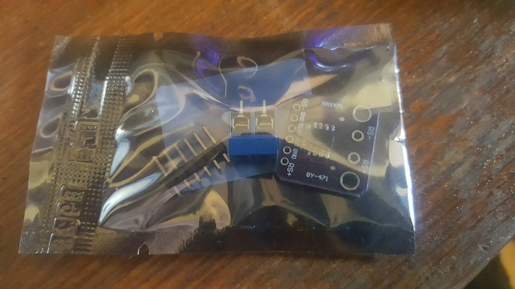
The GY-MAX471 Voltage and Current Sensor Module

I found another cheap, interesting module on ICSTATION. This one utilizes the MAX471 chip to sense the voltage and current running through the circuit. The datasheet for this module is non-existent as far as I can tell, but there is a datasheet for the MAX471, so with some guess work I hooked it up to my UNO.
This is all the info about the module itself that I could find:
1.Size:19.5*20.3mm
2.Test Voltage range:DC 3-25V (Arduino work on 5V) or DC3-16.5V (work on 3.3V)
3.Test Current range:DC 0-3A
4.Chip: MAX471
There are similar modules that also utilize the MAX471 with a little bit more documentation available (this video for example), but this one has a couple major differences from other similar modules. The header pins are arranged in different order, and there are a couple more terminals.
I was getting a constant reading of 0 from the OUT pin, which I am assuming is the current reading. This was likely due to the fact that I was not drawing enough amperage with the LED to trigger a result. It could also be that something is not working correctly, I would have to test it out with something that draws more a few hundred mA or more to be sure. If I ever get around to that I’ll be sure to update this article and post the results.
In the video below you can see the GY-MAX471 in action:
The sketch for voltage test only:
#define vtpin A0

#define Arduino_Voltage 5.0
void setup() {
pinMode(vtpin, INPUT);
Serial.begin(9600);
}
void loop() {
int v = analogRead(vtpin);
double voltage = v * (Arduino_Voltage / 1023.0) * 5;
Serial.print(voltage);
Serial.println('v');
delay(3000);
}
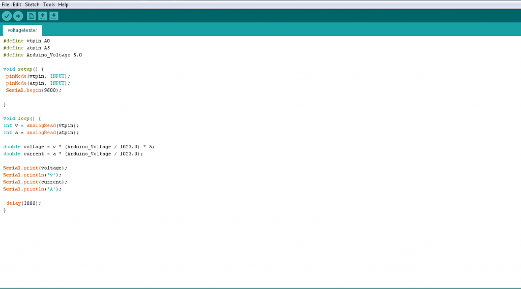
The sketch for voltage and current test:
#define vtpin A0

#define atpin A5

#define Arduino_Voltage 5.0
void setup() {
pinMode(vtpin, INPUT);
pinMode(atpin, INPUT);
Serial.begin(9600);
}
void loop() {
int v = analogRead(vtpin);
int a = analogRead(atpin);
double voltage = v * (Arduino_Voltage / 1023.0) * 5;
double current = a * (Arduino_Voltage / 1023.0);
Serial.print(voltage);
Serial.println('v');
Serial.print(current);
Serial.println('A');
delay(3000);
}
The sketch for voltage current and watts:
#define vtpin A0

#define atpin A5

#define Arduino_Voltage 5.0
void setup() {
pinMode(vtpin, INPUT);
pinMode(atpin, INPUT);
Serial.begin(9600);
}
void loop() {
int v = analogRead(vtpin);
int a = analogRead(atpin);
double voltage = v * (Arduino_Voltage / 1023.0) * 5;
double current = a * (Arduino_Voltage / 1023.0);
double watts = current * voltage;
Serial.print(voltage);
Serial.println('v');
Serial.print(current);
Serial.println('A');
Serial.print(watts);
Serial.println('W');
delay(3000);
}
In summary, this is a pretty handy module. But do beware, in the MAX471 datasheet from the company maxis, they warn that they have discontinued production of the max471 chip, so don’t base any new designs off of it. So if you are using this in single project that doesn’t have to be reproduced many times, this is great option for testing the voltage and current, but if you are looking to prototype something that will eventually go into production, it’s probably best to look elsewhere for a way to handle this. I personally think it’s going to work great for my robotics project where I will run a shutdown sequence if the circuit is under-powered due to a low battery charge.


Kevin, Can you post schematic so I can see where/ow you connected pin 5 for current.
Great article post for current testing module. I really enjoyed reading this blog post. Very useful information and informative post. I love this blog! It’s fantastic!
Thanks for sharing!!!!!!
There is a 2K resistor between GND and OUT
Is this the reason why my current (A) readings are off by 10mA?
I get 14mA on my ammeter and the max471 is giving me 4.8mA. My power is 5v and my load is an LED with a 220ohm resistor. Voltage across the led is 2v, 3v across resistor.
Yes sure, datasheet is available here: http://www.qsl.net/n9zia/28vdc/MAX471-MAX472.pdf
Have you ever checked the values you get from this sketch with a real Voltmeter and Ammeter?
Thanks for sharing!
I have read the datasheet of the M471 in full and I just wonder how you could measure anything out of the sign since this is an open collector which triggers when current above ca 4mA is passing in the load. Moreover I still wonder where the calculations come from, it is unlikely anything related in the datasheet, I have tried this sketch with no reliable results at all. Why do you set the variable ‘arduino voltage’? Where does the 1023.0 value comes from? I am going to experiment with the data in the datasheet to make it reliable or at least, working. Cheers.
The sketches here work for me, if you post your sketch you are working on perhaps I can locate the issue. Also at the time I wrote this article, I could not find a datasheet on this module, can you please share the link to the datasheet? Thank you!
Hi,
How did you connect is AT/VT (or A0/A5) to the module ?
The pinout on the module seems to be RS+,GND,OUT,SIGN,GND,RS-
Regards
Protte