The GY-MAX471 Voltage and Current Sensor Module

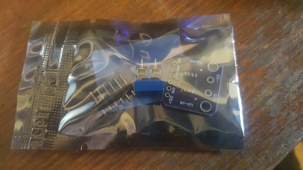
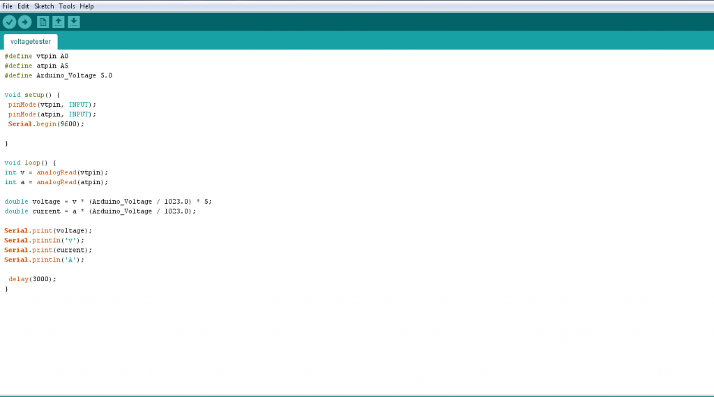
I found another cheap, interesting module on ICSTATION. This one utilizes the MAX471 chip to sense the voltage and current running through the circuit. The datasheet for this module is non-existent as far as I can tell, but there is a datasheet for the MAX471, so with some guess work I hooked it up to my UNO.
This is all the info about the module itself that I could find:
1.Size:19.5*20.3mm
2.Test Voltage range:DC 3-25V (Arduino work on 5V) or DC3-16.5V (work on 3.3V)
3.Test Current range:DC 0-3A
4.Chip: MAX471
There are similar modules that also utilize the MAX471 with a little bit more documentation available (this video for example), but this one has a couple major differences from other similar modules. The header pins are arranged in different order, and there are a couple more terminals.
I was getting a constant reading of 0 from the OUT pin, which I am assuming is the current reading. This was likely due to the fact that I was not drawing enough amperage with the LED to trigger a result. It could also be that something is not working correctly, I would have to test it out with something that draws more a few hundred mA or more to be sure. If I ever get around to that I’ll be sure to update this article and post the results.
In the video below you can see the GY-MAX471 in action:


